Proper characterization of a power supply is critical to ensure that the design meets or exceeds the requirements of the application. This is especially true for Switch Mode Power Supplies (SMPS). Here we have collected content that is specifically designed to guide you through many of the test challenges presented when trying to accurately characterize a power supply.
Power Supply Stability
A good power supply design should deliver the required voltage and current values consistently over the range of load impedance values that are expected. An unstable supply cannot regulate the output well which can lead to the circuit being fed by the supply to behave erratically or to not function at all. Luckily, there are easy tests that can be performed to test your design and ensure stability across the required load impedance range.
Power Supply Stability: Load Step Response
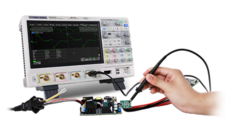
A good primary test to power supply stability is the load-step response. In this test, a DC electronic load is used to provide a changing load to the supply-under-test and an oscilloscope is used to measure the supply response.
Power Supply Stability: Bode Plot
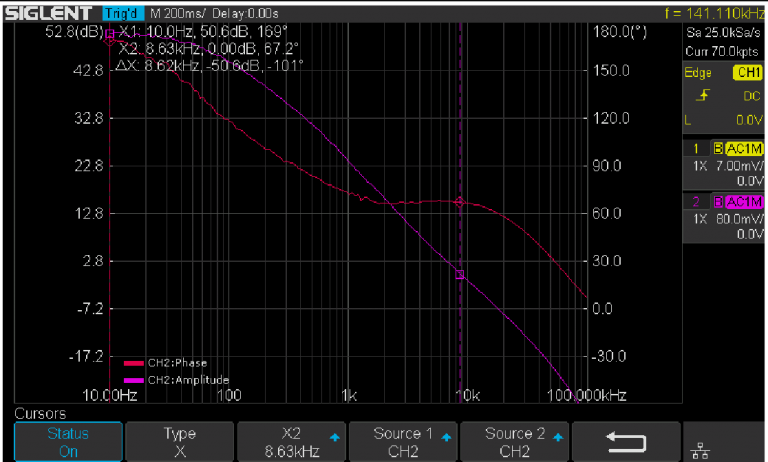
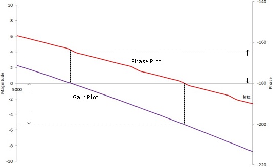
Another common method of determining power supply stability is to perform a frequency response curve or Bode plot on the power supply.
In this process, a known signal is injected into the design, and the resultant output amplitude (gain) and the phase shift are measured. The frequency of the known signal is changed, amplitude (gain) and phase are measured again. This process is repeated until the operating frequency range is covered. Then, the gain and phase data is plotted on a common frequency axis where the data can be analyzed for stability.
Power Supply Efficiency:
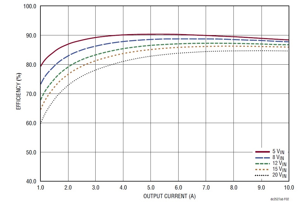
Many electronic designs require a power supply that delivers a known voltage over a specific range of current loads and conditions. In many instances, the efficiency of the supply is an essential characteristic of the design. More efficient designs covert the input power into a higher percentage of output power than less efficient designs. Since the majority of power supply losses are generated as heat within the supply, more efficient designs tend to run cooler, offer higher stability, and longer operating lifetime. More efficiency often just makes more sense. This is especially important for applications that require battery power like remote IOT sensing or communications modules that need to be operational for an extended length of time.
In order to make more efficient designs, we need to know how to measure power supply efficiency.
Here is a note that describes how to build your own power supply efficiency system using common test instruments.
Here is a programming example for creating your own automated power supply efficiency system with Python.
Power Supply Analysis:
Power converter design has become an important part of electronic product development. Modern design needs have increased the importance of power supplies that have greater efficiency, more reliability, with lower electromagnetic emissions (EMI) than past designs. This is especially true for designs implementing Switch Mode Power Supplies (SMPS) that can be especially noisy. Highly specialized Power Design Engineers can measure many of the parameters of SMPS manually, but this is extremely time-consuming and inconvenient.
To help minimize time-to-market and maximize Engineering efficiency, the SIGLENT SDS6000A, SDS5000X and SDS2000X Plus oscilloscopes now offer a Power Analysis option to standardize, automate and speed measurements and simplify power supply testing.
More information can be found in the datasheet for the Power Analysis option available on SIGLENT SDS6000A, SDS2000X Plus and SDS5000X oscilloscopes.
You can learn more about the products discussed in these notes using the links below:
Oscilloscopes
DC Power Supplies
DC Electronic Loads