Double Pulse Testing Solution
October 15, 2025
1 Overview
In recent years, driven by surging demand in industrial control systems, new energy vehicles, and renewable power generation sectors, the market for power devices has grown significantly, while performance expectations for these components have become increasingly stringent. As a critical subset of semiconductor devices, power devices are primarily designed to enable high-voltage and high-current power conversion and control, capable of withstanding substantial power loads.
Power devices currently comprise the following primary categories:
- Diodes: Leveraging their unidirectional conductivity, these devices are critical for circuit rectification, voltage regulation, and similar applications.
- Transistors: Key types include Bipolar Junction Transistors (BJTs) and Field-Effect Transistors (FETs), widely employed in amplifiers, audio systems, and power regulators, used for power amplification and switching circuits.
- Thyristors: This family includes Silicon-Controlled Rectifiers (SCRs), Triacs (TRIACs), and Gate Turn-Off Thyristors (GTOs), predominantly used for AC voltage regulation and controlled rectification in power conversion systems.
- MOSFETs (Metal-Oxide-Semiconductor Field-Effect Transistors): As unipolar devices, MOSFETs are distinguished by fast switching speeds, low driving power, and high input impedance—making them ideal for high-frequency applications such as high-frequency switching power supplies, DC-DC converters, and motor drives requiring rapid switching.
- IGBTs (Insulated-Gate Bipolar Transistors): These devices combine MOSFET and BJT technologies, offering the best of both: high input impedance from MOSFETs, low conduction losses from BJTs, and robust voltage withstand capability. They are widely adopted in high-voltage power electronics applications.
- New-Generation Silicon Carbide (SiC) and Gallium Nitride (GaN) Power Devices: Power devices made from new wide-bandgap semiconductor materials, they exhibit characteristics such as high voltage resistance, low on-resistance, high switching frequency, and high-temperature tolerance. They are widely applied in new energy vehicles, charging piles, solar inverters, industrial power supplies, and other fields. Among these, electric vehicles represent the most critical application scenario for new power devices under the trend of high-voltage fast charging, and the adoption of 800V SiC platforms is also driving the development of SiC power devices.
2 Challenge
As the core method to evaluate the dynamic characteristics of power devices, double pulse test faces multi-dimensional technical challenges in practical applications, which involves not only the complexity of hardware design, but also the precision of test methods and data processing.
2.1 Accuracy requirements of high frequency signal capture
The switching speeds of new wide-bandgap devices (such as SiC and GaN) can reach the nanosecond level, necessitating test equipment with high bandwidth (typically requiring over 500MHz) and low-noise characteristics. For instance, the reverse recovery time of GaN devices can be as short as below 10ns. Insufficient bandwidth can lead to waveform distortion and misjudgment of switching losses. The SDS5000X HD series oscilloscopes from SIGLENT, featuring a 12-bit ADC and 1GHz bandwidth, can accurately capture the test waveforms.
2.2 Technical difficulties of common-mode interference suppression
In high-power testing, the common-mode voltage can reach the kilovolt level, making the common-mode rejection ratio (CMRR) of differential probes a critical parameter. For example, when testing an 800V SiC platform, the CMRR of traditional differential probes may drop below 60dB in the high-frequency band (such as 100MHz), leading to false oscillations in the Vgs waveform. To address this challenge, SIGLENT has launched the ODP6000B series of optical isolated probes. With a CMRR of 160dB and fiber-optic transmission technology, these probes can effectively suppress interference and accurately reproduce the true waveform.
2.3 Intelligent requirements of data processing and analysis
Double-pulse testing requires the synchronized analysis of dozens of parameters, such as switching times (e.g.: tr, tf), energy losses (Eon, Eoff), and voltage/current change rates (dv/dt, di/dt). Manually organizing multiple sets of test data and generating reports consumes a significant amount of time and is prone to data errors and omissions. SIGLENT DPT software, through its built-in algorithms, can automatically identify characteristic of waveforms and generate customized test reports that include waveform screenshots、parameter tables. The report can be exported in HTML or XML formats, improving efficiency by over 80% compared to manual analysis. This function greatly improves the test efficiency and reduces the manual operation error.
3 Solution
3.1 Test Items
The types of switch devices to be tested include MOSFET or IGBT, and the following parameter analyses are supported:
| Switching Parameter Analysis | Switching Timing Analysis | Diode Recovery Analysis | Capacitance Analysis |
| Turn-on energy (Eon) Turn-off energy (Eoff) Peak voltage (Vpaek) Peak current (Ipeak) | Turn-on delay (Td(on)) Turn-off delay (Td(off)) Rise time (Tr) Fall time (Tf) Turn-on time (Ton) Turn-off time (Toff) The rate of change of drain-to-source voltage or drain current between specified levels (d/dt) | Reverse recovery time (Trr) Reverse recovery charge (Qrr) Reverse recovery energy (Err) Reverse recovery current (Irrm) The rate of change of reverse recovery voltage or current between specified levels. (Diode d/dt) | The charge that must be supplied to the parasitic output capacitor of the power device in each switching cycle(Qoss) |
3.2 Test Equipment
The Double Pulse Test is a commonly used test for analyzing the dynamic characteristics of power switching devices such as MOSFETs and IGBTs. Through the Double Pulse Test, the performance of power devices can be conveniently evaluated, and key parameters during both steady-state and dynamic processes can be obtained. This enables a better assessment of device performance and facilitates the optimization of drive design, among other benefits. To perform the Double Pulse Test, the following equipment is required:
| Equipment and software requirements | Quantity | Note |
| High performance oscilloscope SDS5000X HD | 1 | Double Pulse Test Analysis Software integrated in. |
| High-voltage power supply | 1 | SPS series :supplying voltage to the inductor |
| DC power supply | 1 | SPD series : supplying power to the gate driver |
| Arbitrary waveform generator | 1 | SDG series: generating a double-pulse signal with the desired amplitude and pulse width. Provide excitation to the gate driver of the power device to measure the device’s switching, timing, capacitance, and reverse recovery parameters. |
| High-voltage differential probe | 1 | DPB series: used to measure high-side or low-side voltage Vds. |
| Current probe | 2 | CP series: used to measure current Id、Irr |
| Passive probe | 1 | Standard Accessories, used to measure voltage Vgs. |
| DF2001A deskew fixture | 1 | Calibration of time delay between any two different oscilloscope channels (including probe and probe cable). |
3.3 Test Steps
3.3.1 Test connection diagram
For the connection mode of double pulse test, please refer to the following figure:
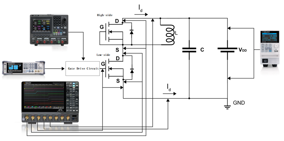
Test wiring diagram
3.3.2 Generation of double pulse signal
In the Double Pulse Test, two pulses with different pulse widths are required. The first pulse is used to establish the initial state, allowing other components in the circuit to reach a relatively stable operating temperature and reducing the impact of temperature variations on the test results. Simultaneously, it establishes a certain current through the inductor in the circuit, creating conditions for the test with the second pulse. The second pulse is employed to test the dynamic characteristics of the power device. During this phase, an oscilloscope and probes are utilized to measure the voltage and current parameters of the device during switching. The turn-off process of the power device is observed at the falling edge of the first pulse, while the turn-on process is observed at the rising edge of the second pulse.
This special pulse sequence can be edited and generated in software, with the parameters of individual pulse adjusted. The resulting file can then be imported into an arbitrary waveform generator for output. However, this method is rather cumbersome and inconvenient for parameter adjustment. The SIGLENT arbitrary waveform generator has a built-in multi-pulse feature. It displays the characteristics of the output double-pulse waveform intuitively on the signal source interface, and allows for more convenient setting of parameters such as pulse width. The interface is easy to operate with clear guidance, saving engineers’ time and enabling them to focus more on power device testing as well as debugging and resolving issues.
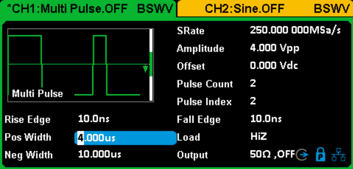
Multi-pulse output setting interface of AWG
In the multi-pulse interface, users can select the number of pulses, and set the relevant rise/fall times and positive/negative pulse widths for each individual pulse. The interface is simple and the operation logic is clear.
3.3.3 Double pulse test software
On the oscilloscope, SIGLENT provides testing software for double pulse test, which can effectively shorten the testing time.
Click Analysis →Double Pulse Test to open a specific test window. According to the test process, it is divided into five steps: Setup, Test Select, configure, Deskew, and Target
3.3.3.1 Setup
- Provides three functions of setting: Recall, Last and Save.
- There are two options to provide DUT Type selection: MOSFET、IGBT.
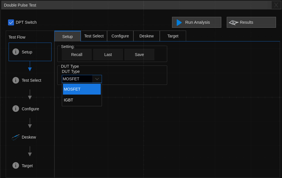
Window of Setup
3.3.3.2 Test Select
Select the items to be tested in this column.
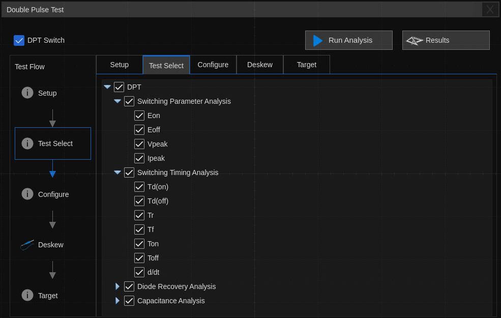
Window of Test Select
3.3.3.3 Configure
The previously selected test items will be highlighted in this section. By clicking on them, you can configure the corresponding test parameters, such as setting the source for voltage /current measurement, max voltage, etc. The oscilloscope will automatically measure the items according to the settings here. At present, only one-sided switch parameter analysis is supported. Please replace the test wiring as required.
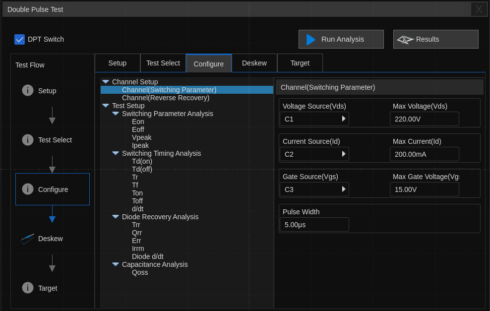
Window of Configure
3.3.3.4 Deskew
A relatively small time delay between voltage and current can lead to significant measurement errors. Deskew Calibration can be performed to correct the time delay of an oscilloscope or probe. When the power device is a MOSFET, calculate the time delay for the Vds voltage channel and the Id current channel. When the power device is an IGBT, calculate the time delay for the Vce voltage channel and the Ic current channel. Deskew can be carried out in conjunction with the DF2001A test board. Refer to the “Switching Loss” section in the power analysis part of the user manual for more detailed information on Deskew Calibration.
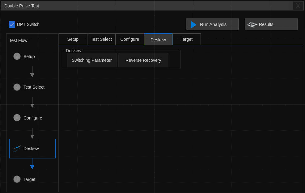
Window of Deskew
3.3.3.5 Target
Click Target to enter the page and set the Analysis Target:
l New Frame: Oscilloscope automatically sets parameters to collect signals according to channel configuration, and then performs analysis.
l Current Frame: Users manually collect a frame signal according to the channel configuration, and then perform analysis.
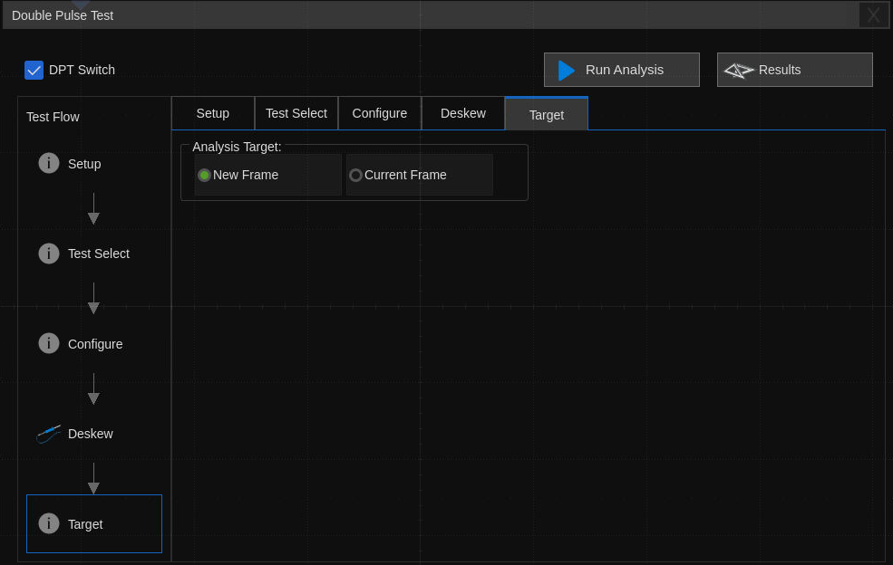
Window of Target
3.3.4 Test Result
After clicking Run Analysis, please follow the prompts:
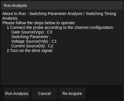
Window of Run Analysis
After the test analysis is completed, click Results to view the test results. The upper part of the test result window is the test items, which provide the test conditions, measured values and pulse region of each item. The lower part has the report setting area and the waveform of the test. Click on the item of interest in the upper part, and the corresponding screenshot will be displayed in the lower part. Click on the picture to enlarge and view the details of the test waveform.
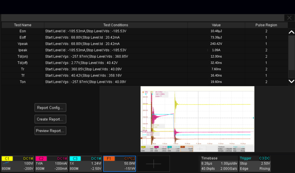
Test Results List
3.3.5 Test Report
Every time an analysis is performed, the test results will be overwritten. If you need to keep the test results, you can save the report. Click Report Config… to edit the test information in the pop-up dialog box. Click Create Report… to select the saving path, and click Preview Report… to view the complete report on the oscilloscope.
The test report includes a summary table of all test results. Click the name of the test item to quickly jump to the details page, which includes a screenshot of related test waveforms.
Note: When saving in HTML format, a folder and an HTML file will be generated. If you need to copy the results, you need to copy them both and keep them in the same path.
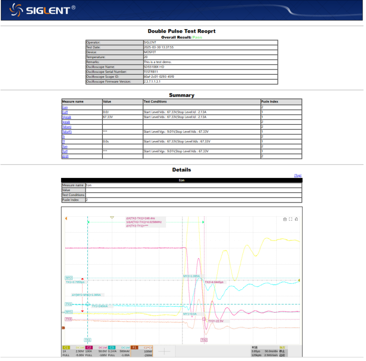
Test Report
4 Summary
SIGLENT offers relevant solutions for power device testing, with double – pulse testing being the primary method for measuring the dynamic parameters of power devices, capable of accurately characterizing their related properties. However, constructing the double – pulse signals required for testing and measuring the relevant parameters have long been challenging difficulties for many engineers. SIGLENT arbitrary waveform generator provides a multi-pulse waveform setting interface, offering users a quick and convenient way to edit pulse signals. Meanwhile, the oscilloscope from SIGLENT includes a double – pulse test application, enabling convenient measurement of parameters in double – pulse testing, reducing testing time, and providing intuitive test result reports.